Dual band rectangular loop antenna for 15m and 10m
This is the second article describing the two antennas that were used by the Carleton University Amateur Radio Club (CUARC) at Field Day 2010. The first post described an off-centre fed dipole with a 200 ohm feedpoint impedance. This post describes the second antenna a loop antenna that worked on two bands, 15m and 10m.
I like loop antennas. I have built large loops for amateur bands, as well as small loops for receiving (which are quite different to their bigger cousins) and have found both types perform well. They are less sensitive to local noise, so often giving good signal to noise ratios. As CUARC was to operate on 10m and 15m at the Field Day site I was considering a loop for one of these bands, however, which one? 10m could be fun if there was an opening, plus the antenna would be smaller than 15m. However, 15m would be more likely to be open. In searching the internet I came across a potential solution as KT4QW’s website who describes a 17m and 10m hanging loop antenna. The idea was simple and elegant, two vertical and rectangular loops fed from the same point, similar as to how multi-band dipoles can be fed from the same feedpoint (sometimes called a fan dipole).
I went about calculating the basic design. A full-wave loop’s total perimeter length is calculated by:
Length (in feet) = 1005 / f,
where f is the intended frequency of operation in MHz.
So for 21.3 MHz that would be a total loop length of 47.2ft and for 28.5MHz it would be 35.3ft.
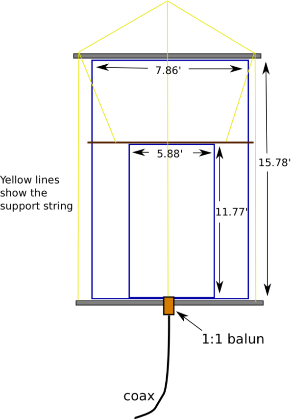
To attain a 50Ω feedpoint the loop needs to be rectangular, with the longer length vertical. Studying J. Carr’s Loop Antenna Handbook and KT4QW’s dimensions the sides were close to being 1/3 of the total loop length for a vertical side and 1/6 for the horizontal side. So this then gave a design as shown below.
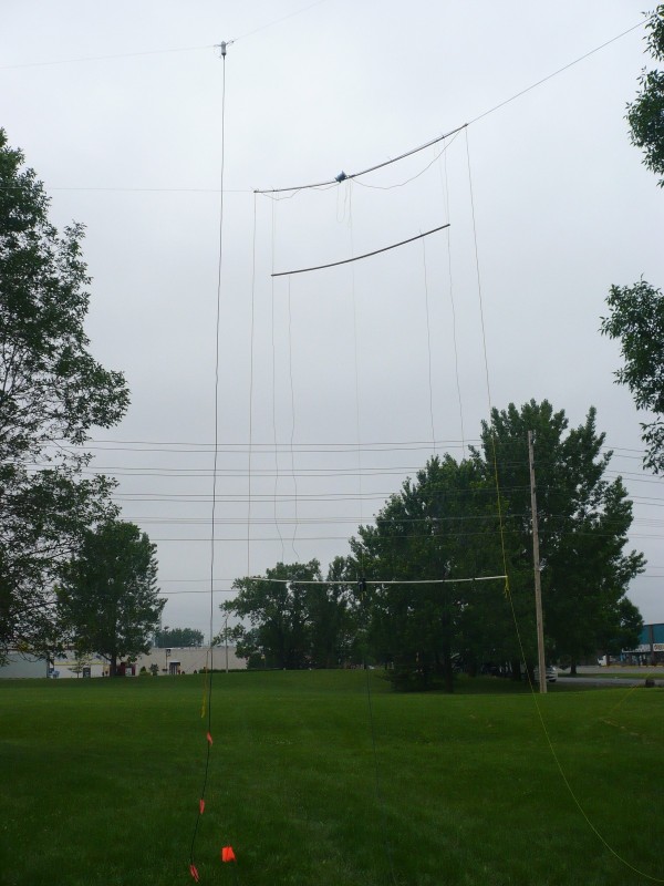
To support the wire I bought two 10ft lengths of PVC piping. The inner support for the upper part of the 10m antenna was some thin wood. Both the wood and PVC were drilled with holes prior to Field Day. The wire was cut from a single 100ft roll and the whole antenna was built by CUARC members at the Field Day site on the day. At the feed point a 1:1 balun was used, an Elecraft BL2. The intention was to suspend the antenna from a single central point so the loop(s) could be rotated, using a line tied to one lower corner. However, we could not get enough height and clearance from tree branches, so we mounted it between two trees and it keep it static with the signal projecting in South-West and North-East directions.

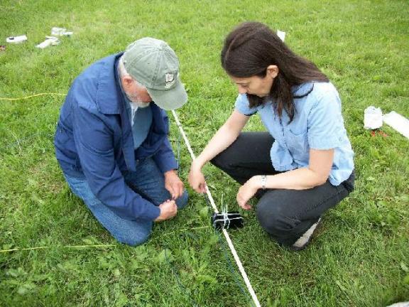
Loop being assembled by Gerry, VA3GLT, (left) and Maria, VA3MMI, (right). (Photograph courtesy and copyright of Chris Wiesner, VA3SM).
After construction the SWR was measured and found to be nicely below 2:1 for both bands (at least the lower part of 10m which is quite a wide band). As mentioned in the earlier post Maria, VA3MMI, brought a portable analyzer to the site on Sunday morning and the trace of the SWR profile is shown below. You can see the antenna has two nice dips in the SWR within the two bands. In an effort to see the usable bandwidth (below 2:1 SWR) the max SWR on the Y axis has be limited to 2.0:1.
To further examine the bandwidth of the two dips in SWR Maria, VA3MMI, set markers at the 2:1 points of the SWR curves. These are shown in the next two traces (one for each band). Both show good usable portions of the bands for phone, see the tables on the right of the trace. (Thanks to VA3MMI for the measurements and traces).
So, with the off-centre fed dipole and this dual loop antenna, CUARC constructed two antennas for Field Day that worked on 15m and 10m without the need of an antenna tuner unit. Performance was good on both antennas and I heard at least one comment that that we had a strong signal (we used 100W). During Field Day we made over 100 contacts on 15m and 16 contacts on 10m. Not bad, as for many of the CUARC members this was their first chance at operating on HF. It was enjoyable for the newly licensed CUARC members to build and then use the two antennas and to find both worked successfully. For me that was perhaps the highlight of 2010 Field Day.


 Subscribe
Hi Allan,
Another interesting antenna, an enjoyable read; thanks.
I have never played around with loop antennas and this is giving me some food for thought. Something similar I stumbled across in one of my ventures round the world of the WWW was about an antenna referred to as the Cob Web antenna. Most variations cover 14, 18, 21, 24 and 28 MHz Bands.
The best reference I have found so far is http://www.karinya.net/g3txq/cobweb/
Small, lightweight, easily assembled. Seems ideal. It looks like a horizontal loop but is really a multi band horizontally orientated multiple dipole antenna. This one is high on my list of things to try – the list seems to get longer every day.
I bought a bare PCB for an AERIAL ANALYSER designed by VK5JST
Details here: http://www.users.on.net/~endsodds/analsr.htm
There is a local ham who has had some input on this design, VA3SMM Stan Madore in Almonte although I have never met the gentleman. Parts collection for this project is progressing in earnest.
I also recently found on eBay a MFJ-202B Noise Bridge for a good price and am patiently awaiting it’s arrival. I have never used one of these before but I do know the basics of their operation and use. Finally I will be able to take a more pragmatic approach to antenna construction and testing than just taking a handful of SWR measurements.
cheers, Graham ve3gtc
Hi Graham,
Glad you enjoyed the post.
The Cobweb antenna looks interesting, thank you for the link. From the quick read I made though it seems to be fundamentally different as the design length of the Cobweb seems to be a dipole length and so when folded into a square it drops the impedance to around 12ohms. As the author points out that can be accommodated with a 4:1 balun. That length difference should make the Cobweb much smaller than the full-wave loop. Could be an interesting antenna especially given the size. I wonder what the pattern would be like? Presumably heading towards omnidirectional which could have advantages and disadvantages.
The aerial analyser also looks interesting. (My British roots like the use of ‘aerial’!). My test equipment for SWR measurements are: the Autek Analyzer, a homebrew bridge that measures forward and backward power (one of the most useful pieces of test equipment I built) or the K2’s SWR reading from its antenna tuner. I will try and make a post about the bridge in the future, That works up into VHF and I have used it with 2m antennas.
Let us know how the analyser works when you get it completed. If you are needing any specific parts let me know as I have a reasonable junk box. Don’t forget the Carp Hamfest is coming up too.
73
Alan
Hi, Alan.
That reminds me a lot of the vertical moxon.
The vertical moxon is about the same size but has excellent front:back ratio and great gain.
Here’s a reference to it:
http://www.moxonantennaproject.com/m3kxz/M3KXZ_VERTICAL.htm
There a million other moxons there too (including some dual and tri-band versions (so 10m/15m/17m is feasible).
http://www.moxonantennaproject.com/
Anyway – good job and a thoroughly enjoyable read.
You know you can build it square and then use a 1/4-wave length of CATV coax to match the 72 ohm feedpoint of the loop to a 50 ohm system ?
73!
Martin.
Hi Martin,
Thanks for the nice comments.
As for the Moxon, remember that has two elements, a bent dipole and a reflector. That can give it a rectangular look if there are supports between the ends of the driven and the reflected elements. But those two elements in a Moxon are not electrically connected. The loop antenna here is a complete loop with no breaks at all except at the balun.
Been studying the Moxon and have a 2m one planned. Got as far as buying the PVC piping and will try building one in the next few weeks.
As for a matching stub, yes they can be useful if you have a feed point of around 120 ohms, which a square loop gives. I have used a 1/4 wave 75 ohm stub with a previous 20m loop. That was a rectangle but was fed on the long side which was parallel to the ground. As a commenter pointed out, feeding on the long side meant I did not get the 50 ohm match. Still the 1/4 wave matching stub did the trick. I still have the stub for use with another antenna, that loop has been brought down and is the pile of antennas that I have rolled up in the garage. A pile that I need to sort sometime!
73
Alan
I have been playing with a 15 meter horizontal skywave antenna the past few weeks myself. I was not able to feed it directly with out using a tuner but it worked well. I picked up the LDG 4:1 balun, placed on my antenna and BINGO!, not tuner needed at all with a 1.5 across all the 15m band. VA3STL gave me the answer I was looking for as to why. I do not have a way to measure antenna impedance, just SWR. I did a square, not a rectangle. The use of 75 ohm to help match is on my to do list. Placing the antenna vertical popped in my head last night after reading about the way the antenna is null in the same plane as the wire. Thanks for the article, I found it this morning. I am going to play with this design for 15. It has bolstered my idea on how functional and practical the idea is.
One of the first things I noticed was the dramatic drop in the noise floor. It made a noticeable difference to the point that I can hear weak signal stations I could not hear on a dipole or vertical before.
I was also able to work stations during the recent JIDX contest when I could not hear Japan before on a 1/4 wave dipole. That was with the antenna just 10 feet in the air.
73
KC5GOI