200 ohm feed point off-centre fed dipole

The off-centre dipole installed on Field Day 2010 (photograph and copyright of Chris Weisner, VA3SM)
As I mentioned in the earlier Field Day 2010 report, the CUARC group built two antennas for the event. In this post I will describe the first one of these, an off-centre fed dipole.
The common place for the feed point of the off-centre fed dipole is at a 1/3 : 2/3 split in the arms. This has the advantage of providing low SWR (with a 4:1 balun) at even harmonic frequencies, such as 20m and 10m for an antenna cut for the fundamental frequency of 40m (around 66ft). Whereas a centre-fed dipole will only have the odd harmonics which for a 40m (7MHz) dipole is 15m (21MHz).
Rather than use the traditional off-centre length split of 1/3 : 2/3 for our Field Day antenna, it was decided to follow the design proposed by Richard Formato, K1POO, in two technical correspondences published in QST 1,2 and followed up with further article with by Dale Gaudier, 3. In this design the feed point is moved closer to the 1/6 point on the short arm, the advantage being stated in the articles that you should get a 200Ω feedpoint there and so a low SWR on 40m, 20m, 15m and 10m bands when using a 4:1 balun, with no need for an antenna tuner unit. The emphasis on the 15m band is intentional as a low SWR on that band is not usually possible with an off-centre fed dipole with the feed at 1/3 : 2/3 and a 4:1 balun. Four bands on one 69 foot wire antenna with no tuner looked very attractive for Field Day.
The antenna was cut carefully prior to Field Day and the end insulators were added. When cutting the antenna the length measurement included the ‘pig-tail’ connections that I have on the 4:1 balun. The diagram below shows the arrangement of the antenna.

The off-centre fed dipole for 40m, 20m, 15m and 10m
On the day the antenna was installed between two trees at about 35ft off the ground. While the second antenna was being constructed (to be featured in a later post) its SWR was measured with my Autek RF-1 antenna analyzer. The results were taken by Maria, VA3MMI and Gil, VE3JRY and are tabulated below.
_______________________________________________
Band (m) 2:1 VSWR Range (MHz) Minimum VSWR
40 3.1 : 1 (at 7.38 MHz)
20 13.29 – 14.65 1.4 : 1
15 21.20 – 22.31 1.5 : 1
10 27.78 – 29.25 1.7 : 1
_______________________________________________

Maria, VA3MMI and Gil, VE3JRY record the SWR (photograph and copyright of David Scott, VE3ZZU)
The overall results were very pleasing, although the 40m band was a little disappointing. This higher than expected SWR on 40m was also encountered by Dale, M0AOP/K4DG, and was reported 3 by him to be due to the severe imbalance in the antenna, so requiring a choke balun to remove the stray RF on the coax. We did not try a choke balun, since we were unlikely to operate on 40m, that was another station’s band of operation. However we had an antenna tuner unit if we needed to try and tame the SWR. It was very good to see the SWR profile observed in reference 3 was repeatable.
On Sunday morning Maria, VA3MMI, returned with a portable analyzer borrowed from work and did a sweep analysis. The response is below and markers have been inserted to show the minimum SWR associated with the bands. Thanks goes to Maria for the measurement and the plot.

Off-centre fed dipole SWR plot, with markers.
It would be interesting to remeasure the SWR response again with a choke balun in place. I expect the SWR will drop below 2:1 within the 40m band as found by the author of reference 3. If this does happen then four bands and no tuner needed makes this antenna one for serious consideration on HF. Even without a low SWR on 40m the antenna offers three bands and it performed well on 15m and 10m for us on Field Day.
As a final note, I should reiterate the warning by Dean Straw, N6BV, at the end of reference 1 where he warns about using the antenna on 30m, 17m or 24m, as a very high SWR could damage the balun at the feedpoint.
References
1. “Improved Feed for the Off-Centre-Fed Dipole” R. A. Formato, K1POO, Technical Correspondance, QST, May 1996 p76.
2. “Off-Centre-Fed Dipole Comments, Part 2”, R. A. Formato, K1POO, Technical Correspondance, QST, October 1996 pp72-73.
3. “Choke the OCFD” D Gaudier, M0AOP/K4DG, Technical Correspondance, QST, September 1997, pp82-83.
Note: all three of the above papers are collected together in “More Wire Antenna Classics Volume 2” ARRL, (1999).
The Field Day photographs above are from the Ottawa Valley Mobile Radio Club’s photo gallery.
Special event station N2H at hacker convention

Ed Piskor's QSL card for N2H
The station has a great QSL card (above) which was drawn by Ed Piskor of Wizzywig Comics. Ed shows on his blog how he created the QSL card. I will have to try and catch N2H on the air to get one of those cards.
Great to see amateur radio involved in the hacker scene.
For above image note: Ed Piskor / CC BY-NC-ND 3.0
CUARC’s First Field Day

Field Day 2010 site viewed from the CUARC tent early Sunday morning
Well it has been a week since Field Day (FD) and so it is time I gave a report on how it went.
As previously mentioned I have been involved in establishing an amateur radio club at the university where I work. For this FD, the first one for the club, the Carleton University Amateur Radio Club (CUARC) teamed up with the Ottawa Valley Mobile Radio Club (OVMRC). Since February there have been 14 new amateurs licensed through CUARC so here was a chance for these newcomers to gain some operational experience and to mix with some very experienced amateurs in the OVMRC.
 talking to CUARC members")
Ernie, VE3EJJ, talking to CUARC members (copyright Ziad El-Khatibi)
The site was the very front of the grounds of the Canada Science and Technology Museum, by the lighthouse. We ran a 4A operation as VA3RAM and the CUARC contribution was a 100W SSB station on 10m and 15m. CUARC used two antennas, an off-centre fed dipole and two nested full-wave vertical loops for 15m and 10m. These were built by the students, the dipole prior to FD and the loops on the day. The antenna building was a good exercise, translating theory into practice and the antennas had low SWRs on the required bands of 10m and 15m when checked with my Autek antenna analyzer. There was quite a lot of interest in the antennas from other amateurs and I will describe these in detail in a later post.
On Saturday 10m was open so operations started on that and it was great to see the thrill the CUARC members had when making contacts on the antennas they had built. As the afternoon wore on there was a move to 15m. CUARC members mixed with the OVMRC members and were given the opportunity to run the other stations. A great report on this is given in a post on Bob’s, VA3QV, blog.
 and Campbell, VA3CNS, (right) working 10m (copyright Ziad El-Khatib)")
Gerry, VA3GLT, (left) and Campbell, VA3CNS, (right) working 10m (copyright Ziad El-Khatib)
Field Day is a good time to get operating experience and some of the CUARC members took this opportunity, others were a little ‘mic shy’. One notable operator was Campbell, VA3CNS, who did an excellent job at calling CQ on 15m and logging stations one after another. He was almost running a pile-up for a while. Another highlight was Maria, VA3MMI, working 80m with Bob, VA3QV, and receiving some NTS for the International Space Station. This is detailed in Bob’s blog post. One contact that I made that pleased me was when I was manning Ernie’s, VE3EJJ, 40m station and I logged W1AW. Nice to work a station I had heard so often on CW.
The weather was a little damp and not too hot. Overall, not unpleasant weather which helped to make the 24 hours manageable, even on only three hours sleep.

The busy CUARC tent (copyright Ziad El-Khatib)
Overall a great FD and very enjoyable.
Special thanks to Ziad El-Khatib,VA3ZEK, for most of the photographs.
More on the Minimalist Transceiver

'The Bay' minimalist transceiver (without component values)
Back in March I wrote about my experiments with a minimalist transceiver design that was published in Sprat earlier this year. Today I received an e-mail from Claude, W5FYI, who enquired about this work. He wrote:
I, too, am interested in building G0EBP’s FET transceiver. One thing that puzzles me is reference in the Sprat article to the 560pF C5. Tony says it is for the final filter. Is he referring to the FET’s capacitance, or his value for the pi filter’s capacitors.
When you get your schematic ready, please let me know.
I thought I would share my reply as others may be interested:
Thanks for the e-mail.
Yes I wondered about that reference to C5 too. I presumed it was the 100nF cap connected to the drain and the inductor on one side and the filter on the other.
I have done quite a few mods to this circuit and still tinkering trying to get a 700Hz freq. offset on transmit, so avoiding issues if someone is zero beat. My first attempts were poor, using an idea in Solid State Design for the Radio Amateur, which plays with some feedback in the oscillator circuit (Fig 6 p36 if you have that book). I see a brief freq. shift and then it seems from my freq. counter the oscillator locks back again. Perhaps I need to switch in the capacitance with the crystal which I think will work better. Been too busy recently with work to finish this experimentation.
Back to my main changes that I did.
1. I changed the oscillator to a FET based Colpitts with a J310. Better waveform, but lower output than a 2n2222 and hence only about 1/4W out with 9V.
2. I have used a different muting process. On keydown I put +Vsupply to pin 7 of the LM386. That mutes the audio op-amp. See LA3ZA, Sverre’s notes on this at http://www.qslnet.de/member/la3za/Pixie_mute.htm
3. Rather than have the key in line with the supply I included another transistor (PNP BJT) so key is connected to ground for transmit. This helps if you mount an un-isolated socket for the key jack in a metal chassis.I need to finish off the experimenting with the offset and then write up the changes for SPRAT.
I looked in my notes and see I blocked out the basic circuit but have not added any component values, so I attach it here, to help you. The offset circuitry is not included. I think you will be able to work out the component values from the original diagram. If you need the calculated values for the Colpitt’s oscillator, let me know and I can supply those.
Hope the above helps you.
By the way I have started to call this transceiver “The Bay” after Morecambe Bay where G0EBP lives and coincidentally where I was born and grew-up.
The draft circuit diagram is above. It is unfinished but still gives a good idea of what I have done with Tony’s, G0EBP circuit.
When I get time to return to this circuit I will report findings and updates here on the blog.
Report on my QRSS signal from Michigan

QRSS report from AJ8T
Thad, AJ8T, sent me a nice report on my 30m 160mW QRSS signal. A screenshot of what he received is above and clearly shows the ‘a3stl’ part of my signal. In his e-mail he reported
It was received about 20:40Z on May 26,2010 using Spectran, a Signalink interface, a Yaesu FT-897d and an 80m horizontal loop up about 10m fed by ladder line. I’m located in Sturgis, Michigan (grid EN71hs) half way between Chicago and Detroit.
My transmitter has been running continuously now for a few weeks and it is good to see how stable it is. For those readers unfamiliar with QRSS those frequency changes that give the CW are about 5 or 6 Hz steps. Which gives an idea of the stability, as well as the challenge to detect these signals (the 30m QRSS ‘band’ is just 100Hz wide).
He also reported that he too will be putting a QRSS transmitter on the air soon. I look forward to seeing AJ8T’s signal on the grabbers.
Thanks for the report Thad!
A simple HF receiver
Before this blog I had a web site with some amateur radio information. It is still out there, but I should close it down or update it totally. Here is one of the projects from those pages which I had great fun with and which is worth adding to this blog. I was quite impressed with the quality of the audio from this receiver which has just seven components (three capacitors, two transistors, a resistor and a transformer). Below is an edit of what was originally written a few years ago.
I constructed this simple receiver having seen the circuit at WB4LFH’s web site which he calls the ‘audion’. This circuit is almost identical to the last circuit on that page, except I changed the inductor connection to the variable capacitor from being a tapped connection to being a transformer coupling.
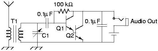
The inductor was a T50-2 toroid with secondary being 28 turns of enameled copper wire and the primary (connected to the antenna) being two turns. (Remember a ‘turn’ on a toroid is the passing of the wire through the hole). The transistors were 2N3904 types, but you can try any general npn transistor. The tuning capacitor was a air plate type taken from an old radio receiver, likely about 300pF. The circuit was constructed ‘ugly style’ on a small piece of unetched circuit board. Use what you have in your junk box and experiment.
The performance is very good considering the simplicity of this receiver. Below are a set of sound recordings from this receiver. The recordings show how the volume can change (no AGC here!) and that the selectivity is not too good.
If you consider building this receiver please note that these recordings were done with the receiver connected to my external antenna at that time, a G5RV. I tried using a long whip antenna, which I had in the junk box, and there was no discernable reception of a signal with it. So you will likely need to use a good length of wire to act as an antenna. Post a comment if you have any success with this circuit.
 Subscribe
